Twirre
Architecture for autonomous vehicles
Project maintained by NHLStenden-CVDS Hosted on GitHub Pages — Theme by mattgraham

Notice
The work on Twirre is an ongoing research project. Your feedback and contributions are welcome!
Summary
Twirre is a flexible architecture for autonomous vehicles using low-cost and interchangeable commodity components. Its initial development platform has been a drone, but the architecture is also suitable for other types of vehicles such as (model)boats and ground vehicles. Several software components have been developed for Twirre, including TwirreLink, a sensor/actuator communication library, and TwirreArduino, which allows an Arduino DUE to be used for sensor/actuator communication. TwirreArduino can also communicate with an instance of TwirreLink running on a main computer through USB. These software components can be used on Windows and Linux (tested on Ubuntu), and have been used on both x86-AMD64 based computers and ARMv7- or ARM64-based computers.
Twirre also encompasses a generic hardware architecture. Reference hardware for the current testing platform will also be detailed. Finally, a PCB design with components list is provided for a ‘shield’ for the Arduino DUE, which provides a cleaner way of connecting various sensors to the microcontroller.
Twirre has been designed and developed by the Leeuwarden (the Netherlands) - based NHL Stenden University of Applied Sciences’s Centre of Expertise in Computer Vision & Data Science. The software is provided under MIT license, and can thus be used easily in both open-source and commercial projects. It is kindly requested to share any useful modifications and additions to Twirre software, for the benefit of all who are (planning to) use this software.

Contents
- Introduction
- Architecture overview
- Software components
- Hardware components
- Licensing
- Demo pictures and videos
- About us
Introduction
In recent years, the usage of drones (or, more generally, Remotely Piloted Aircraft Systems (‘RPAS’)) has been massively expanding. Increasingly affordable and capable small multirotor aircraft have become available. For the field of computer vision, this provides a new way of collecting image data from the air. Drones can for example be used to collect detailed, high-resolution data of agricultural fields for advanced crop health analysis. However, the distance between pilot and aircraft, together with inherent limits of human pilots, presents a limit on the usability of drones for detailed inspection.
For example, inspection of windmill turbine blades for damage requires very high resolution images, which can only be taken from a short distance. This is currently done by an inspector climbing the windmill and manually taking pictures of potential problems using a high-end handheld photo camera. Performing such an inspection using a drone would be much safer and more cost-effective. Some attempts have been made to do this with standard RPAS systems with a DSLR camera attached, but the image quality achieved in that way is generally insufficient due to the pilot not being able to safely fly close enough to the windmill blade. For these kinds of missions, an autonomous drone would be required. That way, the drone can automatically fly at the required distance using distance information from for example depth camera, ultrasonic, or (2D/3D) LiDAR sensors. The drone could perhaps also automatically trace the edges of the windmill blade, ensuring the full surface is captured on camera.
So far, some basic forms of autonomy in drones have become available commercially. This includes, for example, automatic GPS waypoint flight, basic collision avoidance, and target/POI following. For the type of missions described above these are insufficient. Also, that functionality is typically deeply integrated into commercial drones or components, and cannot be adjusted, modified or extended for more advanced purposes.
Some more advanced experiments/research/projects have been published with regards to autonomous control of drones. However, these generally present some other issues:
-
Autonomous functionality is often directly integrated into the low-level flight controller
This makes it more difficult to correct for errors in the autonomous control (especially software bugs causing crash of the flight controller). Also, such functionality is poorly transferable to different models of flight controllers, such as improved models, different drone models, or other types of vehicles.
-
Relying on external equipment
A lot of very impressive demos have been made in specially-equipped rooms with for example an array of cameras attached to the ceiling, allowing fast and accurate determination of the drone’s position and orientation. Although this provides a fairly easy solution to one of the bigger problems of autonomous flight, it means the vehicle cannot easily be used in new locations and severely limits its practical applications.
Similarly, a remote computer is sometimes used to perform the required sensor processing and control logic. This allows a more powerful computer to be used, but also presents limitations due to the required wireless communication link, with limited bandwidth, increased latency, and packet loss or even complete loss-of-link. It also somewhat complicates transportation and deployment of the complete system, increasing mission cost. As such, an on-board computer would be preferrable.
In order to facilitate experiments for more advanced autonomous flight, the NHL Stenden Centre of Expertise in Computer Vision & Data Science has decided a couple of years ago to develop a flexible architecture for autonomous mini-UAVs using interchangeable commodity components: the Twirre architecture. Development started as a small in-house project mainly by internship students, but it has since scaled up to subsidised commercial proof-of-concept projects. During development it was also realised that the Twirre architecture is not limited to UAVs, but can also easily be adapted for other types of vehicles. Subsequently, a project for development of an autonomous model boat has also been started.
Architecture overview
Initial concept, design and enhancement is also detailed in two publications:
- Loosdrecht, J. van de, Dijkstra, K., Postma J. H., Keuning W., Bruin D., 2014. Twirre: Architecture for autonomous mini-UAVs using interchangeable commodity components, International Micro Air Vehicle Conference and Competition (IMAV 2014), August 12-15 2014.
- Boer, J. de, Junyent Barbany, M, Dijkstra, M.R., Dijkstra, K, Loosdrecht, J. van de, 2015. Twirre V2: Evolution of an architecture for automated mini-UAVs using interchangeable commodity components, International Micro Air Vehicle Conference and Competition (IMAV 2015), September 15-18 2015.
The Twirre architecture was designed with a few goals in mind:
- All sensors and processing must be on-board the vehicle
- Use low-cost commodity components
- Upgradeable and extendable
- Useful for multiple applications and vehicle types
- Instant and reliable switching between manual and autonomous control
- Operation in GPS-deprived environments (such as indoors)
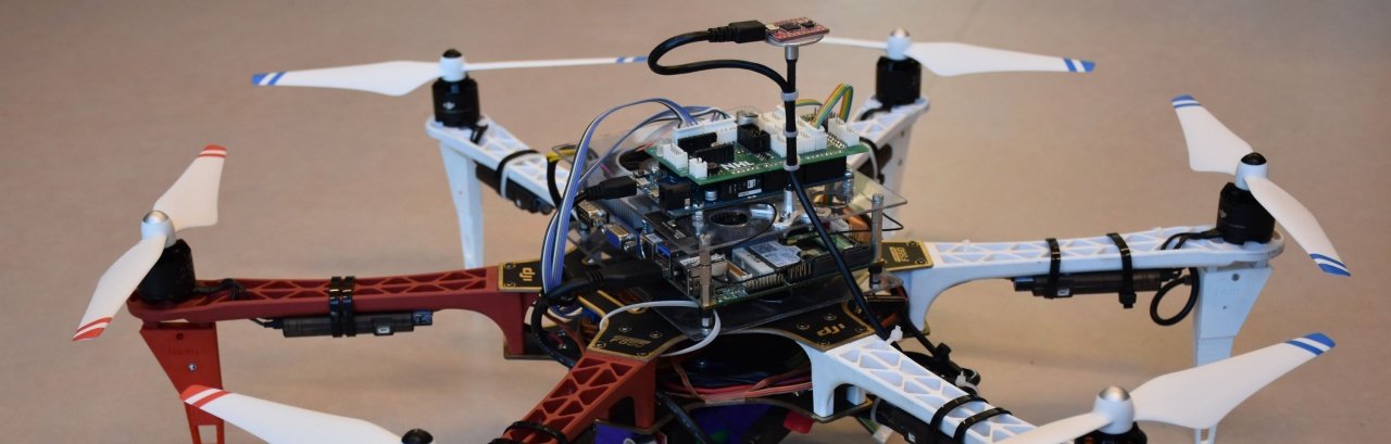
A drone was selected as the initial testing platform. The drone was constructed using a consumer model frame which provides a lot of room for additional equipment (see hardware specs for more information). A typical control architecture for such a drone looks like this:
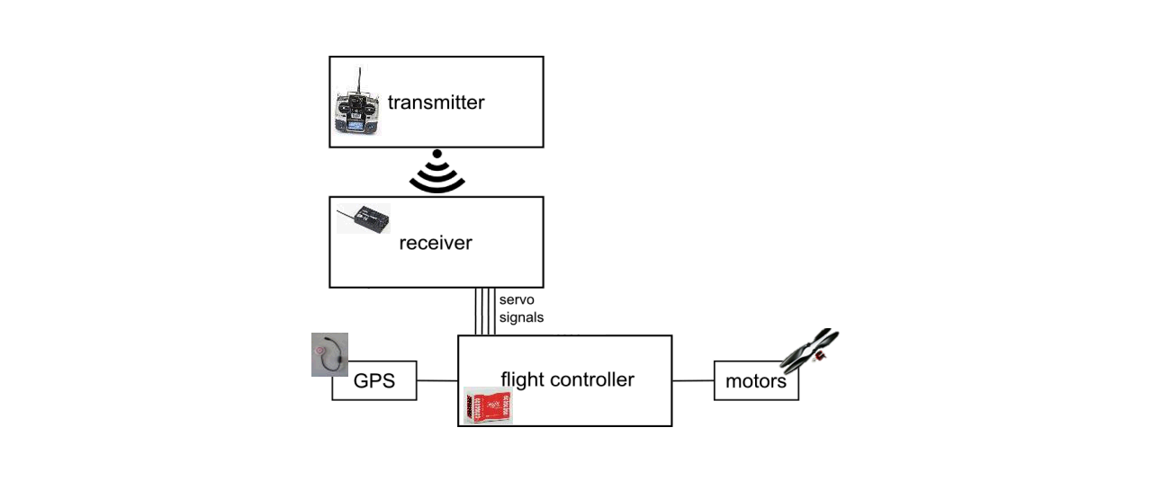
It can be seen that the pilot controls the drone through his transmitter, which wirelessly sends the control commands to the receiver on the drone. This receiver translates the commands into industry-standard servo signals (one for each control channel, of which a drone has four: ‘pitch’, ‘roll’, ‘yaw’, ‘throttle’), which are sent through wires to the flight controller. The flight controller executes the low-level control system, which controls the motors in to match the given control signals. A typical flight controller also contains an intertial measurement unit (IMU) and GPS receiver in order to better control the drone and also provide more advanced features such as auto-leveling (‘ATTI mode’) or GPS-assisted flight.
In the Twirre architecture a couple of hardware components are added to the diagram, making it look like this:
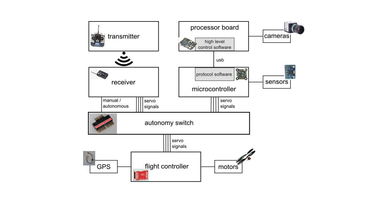
An autonomy switch has been added between the receiver and flight controller. This allows the pilot to switch between two sets of servo signals to send to the flight controller: his own control commands coming from the receiver (manual pipeline), or a second set of servo signals generated by an on-board computer (autonomous pipeline). This switch is controlled through an additional control signal coming from the receiver, allowing the pilot to switch control at all times. The switch is available as a standard consumer component, commonly called a ‘dual receiver controller’, and is normally used for a ‘teacher-student’ setup for flight training, allowing a ‘teacher’ to override the control commands the ‘student’ gives.
The autonomous pipeline consists of two main devices: the main (or ‘host’) computer and a microcontroller. The microcontroller is responsible for generating the servo signals, and also interfaces other sensors (such as a sonar) and actuators (such as a status led). The main computer provides the processing power, and interfaces high-bandwidth devices such as cameras. The main computer and microcontroller can exchange data using specially-designed protocol software (TwirreSerial, part of TwirreLink), allowing the host computer to access sensors and actuators connected to the microcontroller, and decide the control outputs to generate.
In a typical autonomous mission the host computer runs a high-level control loop which determines the current and target position of the drone, and calculates the control outputs required to reach that target position. The position determination can by done by using, for example, computer vision to process camera images and calculate distance and direction to an object of interest.
Note that newer flight controllers also accept control signal types other than servo signals, such as PPM or Futaba S.Bus. In general, the Twirre architecture should also be suitable for those, although a signal generation method for those types of signal has not been implemented yet.
- some initial ideas for a more advanced control software architecture will be given here at a later date, involving a mission state machine and separation between mission logic and position control
Software components
Several software components have been created for use with the Twirre architecture:
This page will only give a short summary for these components. Please check the corresponding repositories for more detailed information.
TwirreLink
The TwirreLink library provides a generic sensor / actuator communication API. It is considered to be the core of the Twirre architecture. TwirreLink also contains TwirreSerial, a protocol for communication over serial links, which is used to add sensors and actuators connected to an Arduino DUE to TwirreLink. The library is (mostly) thread-safe, and has a built-in asynchronous logging system.
Repository: https://github.com/NHLStenden-CVDS/TwirreLink
TwirreArduino
TwirreArduino is an Arduino sketch compatible with the Arduino DUE. It provides communication with several sensors and actuators, and is compatible with the TwirreSerial protocol allowing these devices to be used on the host computer through TwirreLink.
Repository: https://github.com/NHLStenden-CVDS/TwirreArduino
TwirreLogReader
A quick-and-dirty Python file for parsing TwirreLink logs.
Repository: https://github.com/NHLStenden-CVDS/TwirreLogreader
Additional sensor / actuator libraries
Some additional TwirreLink-compatible libraries have been written for communication with specific sensors. These are currently bundled in a single repository.
Repository: https://github.com/NHLStenden-CVDS/TwirreLinkAddons
Hardware components
UAV test platform hardware info
The current Twirre testing platform consists of the following hardware:
Frame
The drone frame has been built using a DJI Flame Wheel F550 ARF kit. This is an hexacopter frame offering enough room for the additional equipment needed for autonomous flight. The frame has been equipped with a DJI E310 propulsion system, which offers improved performance and efficiency over the propulsion system which came standard with the F550 kit. This combination can provide around 4.8kg of thrust. The manufacturer recommends a maximum takeoff weight of 2.4kg, to allow sufficient thrust to be used for manoeuvring.
3D-printed parts
Some parts have been printed using a 3D-printer. This includes an extension for the F550 frame landing legs, and a battery holder. See the corresponding section for more information.
Flight controller
The Twirre UAV uses a DJI NAZA M v2 flight controller. This flight controller is suitable for several different engine setups, including the “Hex V” setup of the F550 kit. The NAZA M v2 supports tradional PWM inputs, as well as S-BUS and PPM inputs. In this case, the traditional PWM inputs have been used, as this makes control signal generation using the Arduino DUE a bit easier. The flight controller also supports a GPS module, which enables a GPS-stabilised flight mode when flying outside, preventing the drone from drifting away due to wind.
The flight controller supports a couple of different flight modes: ‘Manual’ mode, where all position/attitude assistance features are disabled; ‘Atti’ mode, which has attitude assistance where the drone auto-levels and maintains its altitude when the sticks are centered; and ‘GPS’ mode with full attitude and position stabilisation. The Twirre drone operates in ‘Atti’ mode for indoor tests.
Controller / receiver / autonomy switch
The manual control pipeline is provided by a 2.4GHz Graupner MX-12 transmitter, paired with a Graupner gR-12 receiver, which provides six control channels. These channels are all in use on the Twirre drone: Four channels are used for the roll/pitch/yaw/throttle control signals, one channel for the flight controller flightmode, and one channel for control of the autonomy switch. The autonomy switch is an ASSAN Dual Receiver Controller, which supports switching up to seven control channels.
Battery
Twirre is currently powered by a Multistar 4S 8000mAh LiPo battery, which is a weight-optimised four-cell (14.8v nominal, 16.8v max) lithium-ion polymer battery with a capacity of 8Ah. These batteries have a C-rating of 10/20 (which, due to the emphasis on high specific energy, is a lot lower than some other available battery packs), meaning that they support a continous discharge of 80A with peak discharge up to 160A. At a weight of 703g, this battery pack takes up a significant part of the total weight budget. With the current hardware setup, it allows a flight time of around 20 minutes.
Computer
During development, several computer systems have been used:
- Odroid U2 (with 16GB eMMC card, and custom active cooling solution)
- Odroid XU4 (with 32GB eMMC card)
- Commell LS-37BS
The Odroid U2 and XU4 are small single-board computers equipped with quadcore ARM-v7 processors (1.7GHz and 2.0GHz, respectively) and two gigabytes of RAM. The XU4 was a significant upgrade over the U2 due to newer processor architecture and faster memory speeds, but eventually the processing power was considered to be insufficient for the vision processing required for autonomous flight. Because of this, Twirre was upgraded to the Commell LS-37BS industrial 3.5” mainboard. The board has been fitted with the following hardware:
- CPU: Intel Core i7-3820QM (2.7GHz x86-64 quadcore with hyperthreading and turbo up to 3.7GHz)
- RAM: 4GB DDR3 SO-DIMM module
- Storage: 120GB mSATA SSD module
- WiFi: A 2.4GHz and 5GHz compatible 802.11B/G/N WiFi module with two antennas
The mainboard has its own power regulation on-board, so it can directly be connected to the flight battery. Power draw of the complete computer system should be around 60 watts at full load, which, when compared to the total UAV power draw of up to 700 watts, does not impact flight time significantly.
Microcontroller
An Arduino DUE is used. This microcontroller provides a large amount of inputs/outputs, with (amongst other things) two i2c buses, SPI bus, serial bus, and various digital and analog IO pins. This allows a large amount of sensors/actuators to be connected. The control signals for the autonomous pipeline are generated using the Due’s PWM signal generators. For easier connecting of devices to the Arduino DUE, a custom shield (TwirreShield) has been developed.
Sensors
The Twirre test platform is equipped with several sensors (which are not always present on the system at all times, sensor setup is flexible depending on requirements):
 a sonar module which is pointed downwards to accurately determine the altitude of the drone. Connected to the 5V-I2C bus on TwirreShield.

 a 1D point lidar which can be used as alternative to the sonar for measuring altitude. Works at much greater distances. Narrow beam means more work is needed to compensate for pitch/roll orientation of the drone.
 an IMU/AHRS which provides attitude and heading data. Can be connected either to the FAST-I2C bus on TwirreShield, or directly to the host computer using USB.
 a 2D lidar system for detecting walls, objects and obstacles. Connected to the host computer using USB.
 UI-1221LE-M-GL: low-resolution monochrome industrial board-level camera. Mounted facing down with a suitable 8mm m12 lens, and used for optical flow for positioning purposes (sadly, optical flow could not be implemented reliably as of yet).
UI-1241LE-C-HQ: RGB industrial board-level camera. Two are mounted on the Twirre drone: one facing forward for object-of-interest detection, and one facing down for detection of landing site.
UI-1221LE-M-GL: low-resolution monochrome industrial board-level camera. Mounted facing down with a suitable 8mm m12 lens, and used for optical flow for positioning purposes (sadly, optical flow could not be implemented reliably as of yet).
UI-1241LE-C-HQ: RGB industrial board-level camera. Two are mounted on the Twirre drone: one facing forward for object-of-interest detection, and one facing down for detection of landing site.
TwirreShield
Design for a sensor/actuator interface shield for the Arduino DUE.
Repository: https://github.com/NHLStenden-CVDS/TwirreShield
Custom parts for F550 frame
Some custom parts for the F550 frame have been created, and printed out using a 3D printer.
Repository: https://github.com/NHLStenden-CVDS/Twirre3DModels
Licensing
MIT license applies to all Twirre software and hardware schematics. See individual projects for license details.
MIT license example from the TwirreLink project
Demo pictures and videos
Pointerdemo
(July 2017) A demonstration application which was used to prove the Twirre v2 architecture software and demonstrate full autonomous flight. The drone will try to fly at a fixed distance from a ‘pointer’, which is a stick fitted with two different-sized coloured spheres. The spheres allow the drone to calculate a full position solution.
Windmill blade approach
(January 2018) A demo of autonomous windmill blade inspection. The demo is performed indoors (as development is currently more practical there), using a black wooden model of a windmill blade. The drone will search for the blade by slowly rotating, and will then approach the blade and keep flying at a fixed distance. After a certain amount of time the drone switches to landing. Throttle, pitch, and yaw are controlled autonomously, but roll is controlled manually, as the vision processing does not give enough information about sideways position relative to the blade.
Windmill blade scan
(May 2018) Another demo of autonomous windmill blade inspection, performed indoors. First tests of the ‘scan’ phase of autonomous windmill blade inspection, using a LiDAR (RPLidar A1, see Sensors). As a 2D lidar gives issues with pitch/roll of the aircraft, the model windmill blade was found unsuitable for these experiments because the LiDAR misses it frequently. An improvised simulated target using tables is used for experiments instead. The UAV operates in full autonomous mode, except for takeoff and landing which are always performed manually.